Preface
QVD (Quality Virtual Desktop) is a VDI solution focused on Linux. The software is designed to completely virtualize the Linux desktop, so the client systems are able to connect to a central server to load its desktop environment and applications. This means that when the users work from their local machine, all the programs, applications, processes and data used are maintained on the server and executed centrally. Virtualization offers a series of advantages:
-
Users can change between computers in a network and continue working as if they were on the same desktop, with access to all their applications and data
-
Administrators have greater control over the applications that are installed in the users systems, and they are able to manage the users data more easilly to perform backups and virus scans, etc.
-
It is easier for administrators to provide new desktops and deploy applications for the new users
-
There is less downtime in the case of hardware failures
-
Users can make use of a variety of different devices to access their desktop and applications, including laptops, personal computers and smartphones.
-
Users can work securely with the same desktop and applications from a remote location without the need for a VPN
-
The general improvement of the system and the data security
-
Reduction in hardware, maintenance and administration costs
The QVD server visualizes each Linux desktop. This can be achieved using either of the two virtualization technologies available in the product. One option is KVM (Kernel-based Virtual Machine) which is used as a Type 1 hypervisor. The other, and much more interesting possibility, is LXC (Linux Containers). This virtualization helps to maintain the environment of each user as its own discrete entity, to improve security and stability.
Virtualization permits the serving of multiple operating systems or environments to users, depending on their neexs. These are loaded as independent images in the QVD server . These images provide the base for the operating system and the work environment that are replicated for each virtual machine. When a user is connected to the server, making use of the client application, a virtual machine is started only for that user. This provides a "cage" which avoids any irregular behavior from affecting other users. When the user disconnects, the virtual machine can be stopped. On stopping, the environment returns to its original state, except for the user’s own specific information. This means that if the user’s environment has in some way developed a problem, a simple disconnection can return the system to its original state. This provides a greater level of security that if a user was working on an independent workstation.
In order to maintain the user data, such as the desktop configuration, documents and other specific userinformation, there are two options. The first, and most common method, is storing this information in an NFS’shared resource. This way, the data can be stored in a 'NAS device or inside a SAN, where it can be easily controlled. A second option is to load a second image in the virtual machine. This image is persistent, since it can be updated by the user, and the changes are stored for each time the image is loaded. Both methods are equally valid. By keeping the user’s data independent from the image of the operating system, we make sure the, should a system image be damaged or there be a failure of the same, the administrators are able to minimize the disaster recovery time.
The desktop is accessed from each workstation, making use of a client that uses the NX protocol to communicate with the server. The NX protocol is used to manage the remote X-Windows connections and provides a high level of compression which permits high performance even when the desktop is accessed using a low bandwidth connection. In addition, QVD is able to wrap the NX protocol with SSL to encode the connection, so the users can work securely even if they access remotely. QVD provides client software to work with a variety of operating systems and base devices, from Linux to Windows.
1. Summary of the architecture of QVD
A QVD solution is made up of three main components on the server side:
-
QVD Server Node
-
QVD Administration Node
-
PostgreSQL database
Ideally, each of these components should be located in a dedicated server for stability reasons.
Furthermore, although it is likely that we only have one administration node and one PostgreSQL server, it is possible (and advisable) to have more than one QVD Node. Therefore, the majority of installations will require the following extra components:
-
Load Balancer
-
Shared Storage ( NFS, for example )
Using a load balancer in front of the QVD nodes, the client connections can be balanced between the healthy nodes to allow access to the user’s virtual desktop. This reduces the amount of configuration necessary in the client software and also assures the availability of the desktops.
Since each node will require access to the shared resources, such as the disk images for the virtual machines and the home of the users, a system of shared storage will normally be configured to allow such access.
In each of the disk images that are loaded in the virtual machines to serve the desktops, the following component is required:
-
QVD VMA ( Virtual Machine Agent )
This agent is responsible for accepting client connections via a QVD node. It facilitates access to the desktop environment that is being executed in the virtual machine and also allows you to configure access to the printers on the client’s side and perform audio streaming to the same. If the client is the Linux version, it will also manage the redirection of USB devices.
Lastly, we have the component of the client’s side:
-
QVD Client
The client is packaged for several distributions of Linux, for Microsoft Windows and even for OSX. Versions for android and ios also exist, although they are currently atbeta stage.
In most production environments, the architecture of a QVD environment is such that several QVD nodes are going to be running in parallel. The environment is designed to be run with a load balancer, so we can have a high availability solution.
2. The QVD Server Node
A QVD server node is made up of a single binary, the HKD or House Keeping Daemon. This component receives all the connections with a level router 7, the L7R (Level 7 Router), which guarantees that all the clients are routed to the correct virtual IP address that has been configured for the virtual machine of the user that is connected. It is also responsible for authenticating the user before the connection, and establishing the client session. The HKD is listening in each QVD node and for each incoming connection, it executes an L7R process.
The HKD tracks the state of the virtual machines. It is responsible for starting and stopping the virtual machines, as well as monitoring the health of each virtual machine and updating the state information in the QVD database, allowing other nodes and administration tools to work accordingly. In general, the HKD is responsible for the management of the state of the virtual machine.
2.1. Behaviour of HKD
The House Keeping Daemon is responsible for the management of states of the virtual machines based on the information detected inside the QVD database. The HKD consults the database periodically to determine the state of each virtual machine. If the state has been changed by another element, such as the web administration tool or a user connecting, the HKD is responsible for executing the appropriate commands to perform the state change.
When QVD is configured for KVM virtualization, the HKD executes an instance of KVM for each virtual machine that needs to be started, and offers relevant starting options depending on the information obtained from the database.
When QVD is configured for LXC, the HKD will firstly check to see whether the image file has been decompressed in the basefs folder in the area of shared storage, and decompresses the image file if it has not been done yet. The HKD then uses the fuse-unionfs module to perform a bind`type mounting of the image in the basefs folder with an`overlay filesystem that automatically regenerates the initial files system. This mounting is performed inside the rootfs folder in the shared storage. Lastly, the HKD loads the recently mounted image in an 'LXC instance.
When the instance of the virtual machine is started, the HKD will check that the image starts correctly, that it has network connectivity and that the QVD-VMA is running in the virtual machine. If any of these checks should fail, the HKD will block the virtual machine inside the QVD database. After a short period of time, the HKD will kill the virtual machine running.
During each loop that the HKD makes, it checks the state of all the virtual machines that are running. If there are changes in the database, they are performed immediately. If not, it updates the state information in the database.
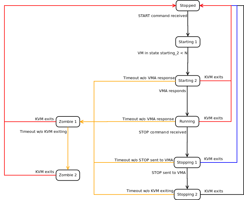
In accordance with the diagram above, these are typical examples of the different maching states that the HKD will return for a virtual machine started through KVM.
-
Stopped: the virtual machine is not running in any host.
-
Starting 1: the HKD has received the order to start, but is waiting until it has the available resources to go to the next state of the machine.
-
Starting 2: the virtual machine has begun the starting process, but it has not finished yet.
-
Running: the virtual machine is running in a server node.
-
Stopping 1: the HKD received the order to stop, but is waiting for the VMA inside the virtual machine to reply to the request.
-
Stopping 2: the VMA has replied to the request to stop and the virtual machine is in the process of stopping.
-
Zombie 1: The virtual machine is running, but is not answering, a TERM signal has been sent to the process.
-
Zombie 2: The virtual machine is running, but is not answering, a KILL signal has been sent to the process.
2.2. Network architecture
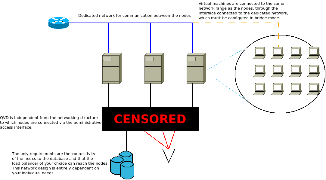
In QVD, a network range is reserved (decided by the Administrator) for the virtual machines. The server nodes must be connected to each other through this range, that is to say, they must have a dedicated network interface connected to it. This interface is used to allow the L7R to channel user connections to the virtual machines, and to let the machines connect to the outside world (if so desired).
|
|
the nodes do not communicate with each other via the network range reserved for the virtual machines. Furthermore, the nodes never communicate with each other . They only listen to changes in the database. |
In general, it is desirable that this range is used exclusively for the virtual machines. However, the range reserved for the nodes (that is from the beginning of the range up to where the administrator configures), can leave space for the services that the administrator deems necessary in this range.
The server nodes require another connection through which they will connect to the database and other services, such as the shared storage or ldap directories. QVD is totally independent from the networking structure in this connection and is dependent on the needs of the administrator.
It is also possible to use more advanced techniques such as vlan-tagging or virtual switching to use a single network port per node. These configurations are more complicated and are outside the realm of this or any other guides that we have published. Moreover, we do not recommend them for the stability of the solution, since crossing user and database traffic could give rise to connectivity problems and nodes going down.
2.3. The QVD Client and relationships between L7R of different nodes
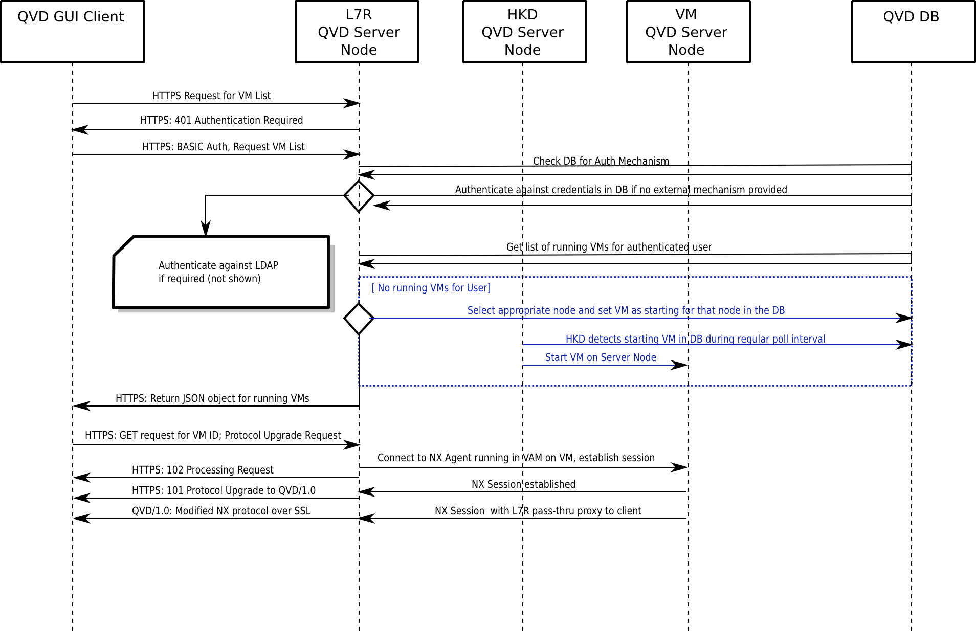
The QVD Client connects directly to the HKD. This produces a fork in the L7R process, broker component of QVD, that will be in charge of managing the rest of the communication with the client. The client initiates a connection via HTTPS, in which it asks for the presentation of basic HTTP authentication credentials.
The L7R will connect to the database to determine the form of authentication that must take place (that is to say, on a local level or using an external LDAP directory) and take the appropriate measures to perform it. The L7R will return an HTTP answer OK if the authentication has been correctly carried out, or will give back a 401 not authorized if the authentication fails.
Once authenticated, the client will ask for a list of virtual machines that are available to the user. The server replies with a list in JSON format of identifiers of virtual machines and their corresponding names. The client selects a virtual machine to connect to and sends a GET request with the identifier of the virtual machine in a standard GET variable. It also asks for an update of the QVD protocol / 1.0 inside the HTTP request headers.
|
|
The L7R supports a structure of authentication by means of plugins. This means that other methods of authentication are supported, such as Single Sign On, authentication by LDAP directories or Active Directory and also authentication in several steps. |
The L7R takes the necessary steps to make sure that the virtual machine is running and waiting for the connections used by the NX protocol. If the virtual machine is not running on a server node, it will determine in which node it should start automatically and a virtual machine will start for that user. In any other case, the L7R will determine in which node the virtual machine is being executed and will resend all the requests to this machine for all subsequent communication, including the checking to see that an NX session can be configured. During this process, the L7R will return a series of answers HTTP 102 which indicate the starting progress and connection with the virtual machine. If the virtual machine is available, the L7R establishes a connection with the nxagent that is executed in the virtual machine and it becomes a transparent proxy type communications channel for the NX session. Once the session is configured, the L7R will emit one last HTTP 101 (Commutation protocols) in answer to the client, and the protocol for all future interactions with the client will be updated to NX, assured by SSL. The L7R updates the QVD database to establish the state of the virtual machine to indicate that a client is connected.
From this point on, all communications between the client and the virtual machine are performed through the NX protocol through the L7R. When the client disconnects, the L7R updates the QVD database to reflect the change in the state of disconnection of the user with respect to the virtual machine.
The process flow is indicated in the following diagram:
2.4. L7R with load balancing
As mentioned previously, the server nodes are designed for an environment with load balancing. With this in mind, the L7R element of each HKD is able to redirect the traffic of a specific virtual machine to any other server node in the environment.
The normal configuration is such that a virtual machine can be started in any of the server nodes. When a user is authenticated through any L7R inside the farm, the L7R determines in which server node the virtual machine is currently being executed to which the user wishes to connect. This is achieved by checking the database. If the virtual machine is confirmed to be running in the environment, the L7R will redirect all the traffic to the appropriate server node.
If no virtual machine is currently running for the user, the L7R uses an internal algorithm to determine the most appropriate node to start a new virtual machine for the user. This algorithm is based on the evaluation of which node has the greatest amount of free resources, calculated as the weighted sum of free RAM memory, unused CPU, and a random number to get a bit of entropy in the result.
When an appropriate node has been selected, the database is updated so that a virtual machine will be started by the HKD in the correct host. The L7R will then redirect all the traffic for that connection to the server node that been selected to execute the new virtual machine.
3. The QVD Administration node
A typical administration node consists of the following components:
-
QVD-API
-
Command line Administration tool
-
WAT (Web Admin Tool)
Each one of these components is independent of the rest, in the sense that they can be installed in different machines. However, both the WAT and the command line tool are independent of the API. This must be installed in at least one node of the installation to permit the functioning of the other two tools. For example, it is very typical to install the line command tool in all the QVD nodes, to help the system administrator with the management of the solution.
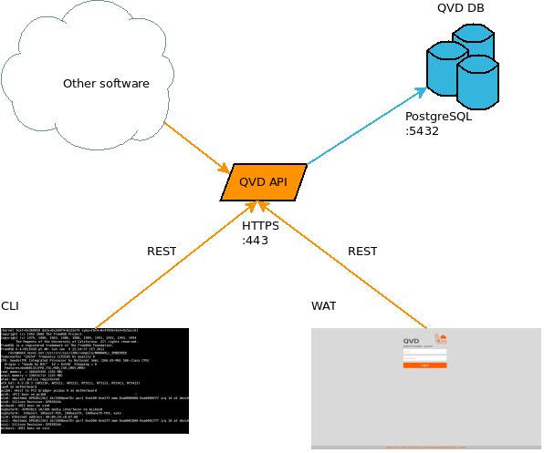
3.1. API
The API is a structural component of QVD. It consists of only one REST interface connected to the database. It is necessary to be able to manage the solution since it is the only way to communicate with the administration tools. It can also be used to integrate the solution with other systems that are able to use the REST interface.
3.2. CLI
The command line tool allows access to the same functions as the WAT, but in the Linux command line. Just like the WAT, it is a client of the API, and cannot work without it. Its use is, of course, more complex than that of the WAT, and so it is probably only used by systems administrators. Furthermore, just like the API, it allows integration with other systems, since it can be used to execute tasks programmatically. Its use in crontab is specially suitable to program different behaviors that can be desirable, such as for example automatically switching off virtual machines that have not been used in some time, deleting obsolete information, configuration checking. or requesting reports.
3.3. WAT
The WAT is the QVD Web administration panel. A web tool to manage users, virtual machines, nodes, images and configuration parameters of QVD
In order to do this, it will show a list on the screen of the system elements with enough information to be able to configure them as well as to detect problems. You also have filtering controls available and a large number of possible actions over the elements of QVD, such as creating, updating or deleting them; and other more specific ones, such as starting or stopping a virtual machine, blocking a user due to maintenance tasks, etc.
In the administration of QVD, the WAT corresponds to the client*part, feeding from the server via HTTP. In this way, it extracts and manages the information of *QVD through authenticated calls to the API of the server. This API also serves the command line administration application(QVD CLI).
3.4. Tenants
4. QVD Database
The database is a standard installation of PostgreSQL. The current version of QVD uses the notification characteristics that are exclusively available from the version 9.2 onwards of PostgreSQL, so this is the minimum version required.
We attach this simplified scheme of the database as a reference, but it will not be described in this document.
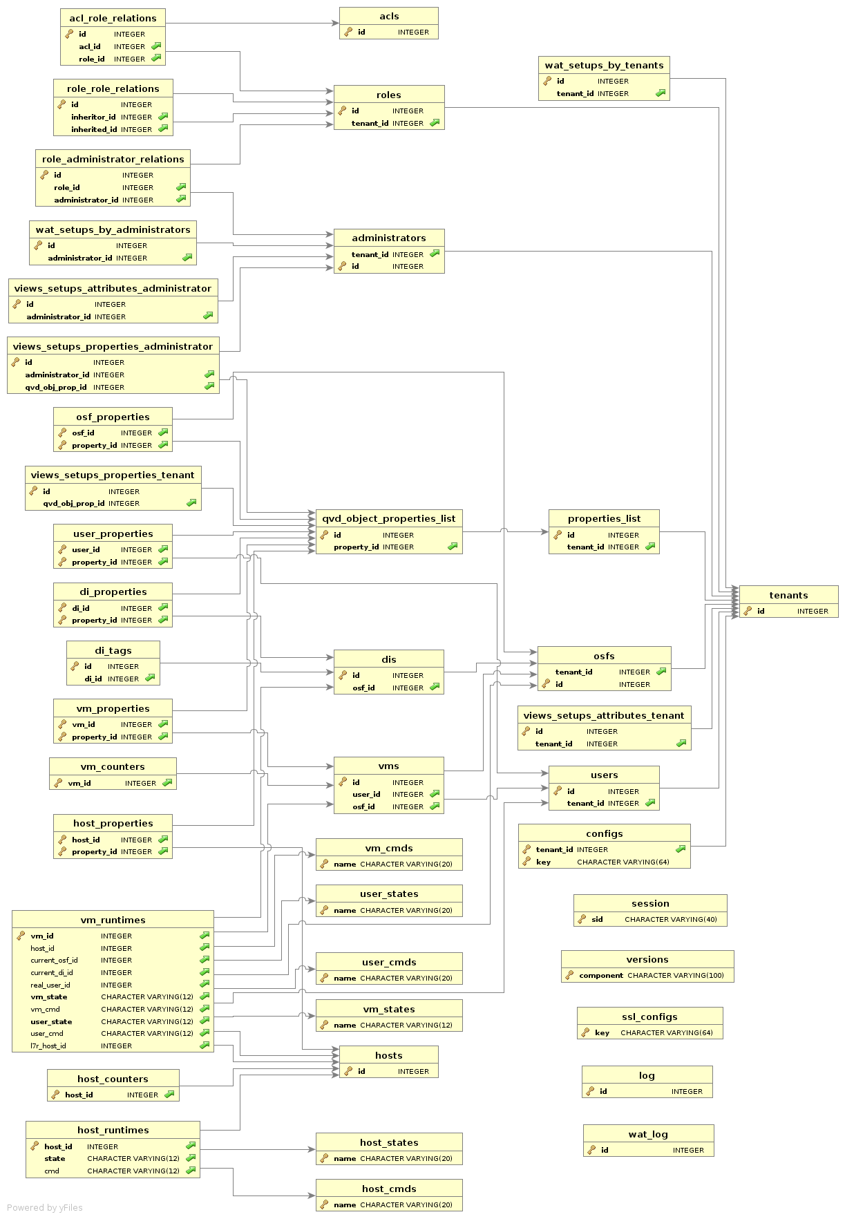
However, some necessary elements will be described to mesh the physical architecture with the functional one.
4.1. Objects of the database
In order to correctly manage a QVD solution, it is important to be familiar with the following database objects and the relation between them:
The DI, as its name indicates, is a disk image of an operating system. The only requirement that they have is to have the VMA installed and configured and a standard Linux desktop which is compatible with the solution. Apart from this, the intrinsic requirements of the type of image that is used (KVM or LXC).
The OSF is a set of resources that the administrator defines to use with a set of images (memory limits, disk and other configurations). When a new image is released, an OSF must be assigned to it. Customized tags can also be added, and if not, the solution will automatically tag it. We will soon see the reason for this.
On creating a virtual machine for a user, an OSF will also be assigned to it. By doing so, when a virtual machine is started, the aforementioned OSF is loaded and all its associated configuration parameters. In addition to the OSF, the virtual machines also have tags associated. It is through these tags that we decide which of the associated DIs to the OSF will be used as the base image of the virtual machine.
The ability to tag is important, since it lets you easily change the versions of the disk images for multiple virtual machines. If a change is to be made in a disk image that is used by a large number of users, the problem can be managed by means of tags. The classic case is to assign a temporary tag to the new image which also has exclusively assigned to it a virtual machine belonging to the administrator. The administrator can now start his machine and check that all is going as expected in the virtual machine. If this is the case, the step to going live is as simple as changing the tag of said DI to that of the machines that the users in production are using. If something goes wrong in the end, the roll-back is as simple as going back to the previous DI tag.
The tag of the DI is only checked when the virtual machine is started. This means that the virtual machines in execution will not be affected by the changes until the user disconnects. For these purposes, the images possess soft and hard expiry times. The combination of both can be used to notify the user that his image has been updated and that he must disconnect when he can, and/or directly force him to disconnect by stopping his virtual machine.
The ACLs are a new characteristic of QVD. In this version a system of strict access control to the solution resources has been programmed. For each installation a list of roles can be defined with a series of permissions assigned, and the administrators can be designated these roles, so they can or cannot execute certain types of actions. This system of permissions has a high level of granularity and allows the solution to be scaled up for a large number of users with administration permissions.
The roles are also a new characteristic of QVD. They permit the definition of predefined ACLs that can be assigned to the users to facilitate the management of the permissions described in the previous section.
Each person requiring access to the solution needs a user account. These accounts are registered in the database, with id, username and password. As with all the other objects in the database, they can be tagged for administrative tasks and scripts that automate tasks. As a note, it is worth mentioning that the password saved in the database does not have to be in use, if an authentication plugin outside the solution is being used(such as LDAP authentication, for example).
A proprietary collection of virtual machines corresponds to each user. To connect, at least one has to be defined. The virtual machines, in turn, belong to a single type of OSF, and they also have a tag, as we commented before. When the solution is asked to start the virtual machine, the image that corresponds to the tag and OSF that are registered for that virtual machine are searched for in the database, and it is used to start it.
The QVD server nodes are also an object in the database. Their IP address and name (which must correspond with the defined hostname in the configuration file of each one of them) are saved . As they are available as configuration objects you are allowed to configure their availability.
5. Virtualization technologies
QVD supports two different virtualization technologies: KVM (Kernel Virtual Machine) and LXC (Linux Containers). Each technology of virtualization has its own set of advantages and each will be more useful for cases of specific use. So, a good comprehension of their own necessities and a comprehension of these two technologies help to determine how to configure the implementation of QVD.
KVM is a Type 1 hypervisor that is executed inside the core of the Linux operating system. The hypervisor guarantees the absolute separation of the underlying operating system, which allows the loading of completely different operating systems in each virtual machine and permits them to work as if they were running in computers that are completely separate.
Although there is some debate as to whether KVM is really a Type 1 hypervisor, since it requires the Linux core in order to work, most virtualization experts agree that combined with the Linux core, the functions of KVM are exactly the same as those of any other Type 1 hypervisor, such as Xen or ESXi of Vmware. In fact, in the SPECvirt 2011 reference reports, KVM came second in terms of performance behind Vmware ESX, which indicates a high grade of viability as a virtualization platform of commercial quality.
Since KVM uses absolute separation, it is much easier to configure and administrate than LXC. However, although it offers a performance to compete with other hardware hypervisors, each virtual machine necessarily executes its own core. The resources must be dedicated to each virtual machine, regardless of whether it is being used or not. Because of this, KVM is not as efficient as LXC, but offers greater flexibility and easy management.
LXC provides virtualization on a system level. In this way, it acts as an alternative to complete virtualization on a hardware level provided by the KVM hypervisor. LXC behaves in a similar way to a caged environment inside Linux, but it offers a higher level of isolation and the management of the resources among the containers through the use of namespaces and cgroups. For example, the process identification numbers (PID), networking resources and support for each container can be isolated from other containers and can be grouped logically to apply resource management rules and other specific policies for each container. This lets you enjoy many of the benefits of virtualization while at the same time maintaining low general resource requirements, as well as letting you to reuse the same core in all the virtual machines. LXC is totally supported by the Linux core and is included in QVD from version 3.1.
6. Virtual machines and VMA
As we commented previously, the HKD is responsible for starting the virtual machines of the users. In a production environment, it is common to have a number of different QVD servers running in parallel. Each virtual machine is a separate instance that is executed in one of the QVD server nodes. If a user connects, authenticates against an L7R and among his virtual machines, asks to connect to one that is stopped, the L7R will use its load balancing algorithm to determine in which node the user’s virtual machine should run and the database will be updated so the virtual machine is started in the appropriate node.
Virtual machines use overlapped assembly points in order to better usethe different elements of the guest operating system and make the user’s data persistent. For example, although the writing activity is not persistent in the real image that is loaded, it is important that the written data written in the user’s home folder are or on the user’s desktop are stored for future connections with the virtual desktop.
Inside the instances of QVD that use KVM virtualization, this is achieved by storing the user’s personal directory inside an image of type qcow2. This is mounted over the user’s personal directory in the image of the operating system that has been loaded in the virtual machine.
In the cases that use LXC, this is achieved thanks to the use of the assembly points of type union_mount (more information in Wikipedia). The data of the the user’s personal directory and the overlay data are stored in an independent directory outside the base image that is used for the virtual machine. These folders can be mounted over the base image at execution time, in order to create a specific container for each user and virtual machine.
|
|
You can also use btrfs (Wikipedia ) to manage the images and assembly points, but will not be discussed in this document. See thelink:/AdministrationManual.html[Administration Guide]. |
The image qcow2 with the user’s personal directory is usually stored in a shared network resource, so it is accessible to any server node in the farm. If the user’s virtual machine is later started in a different server node, the user’s personal directory can be loaded at execution time and the data will always be available for the user. The overlapped assembly points can also be used so that other data, such as logs and temporary files, are persistent from the user’s perspective. This behaviour is configurable and so you can choose if the machines are totally temporary and we do not even save the user’s data, if we save at least the user’s data, or if we save the complete machine with all the changes that it undergoes while running.
Depending on the virtualization technology configured in QVD, the virtual machines will start, using KVM or LXC. However, it is important to understand that the images of these two technologies are very different and it is not possible to switch them.
Once started, each virtual machine must load the QVD-VMA (Virtual Machine Agent) to work correctly. The VMA will ensure that the nxagent component is available for the client to be able to connect to the virtual desktop. It also answers the queries from the L7R, so it can determine the state of the user and the vm, and thus refeeding the database. When an image is created, it is of fundamental importance that the VMA is installed and configured or the image will not be able to be used in QVD at all.
7. High level architecture Diagrams
In this section we will show some simple diagrams that explain the architecture of a typical QVD implementation to show how the different components interact.
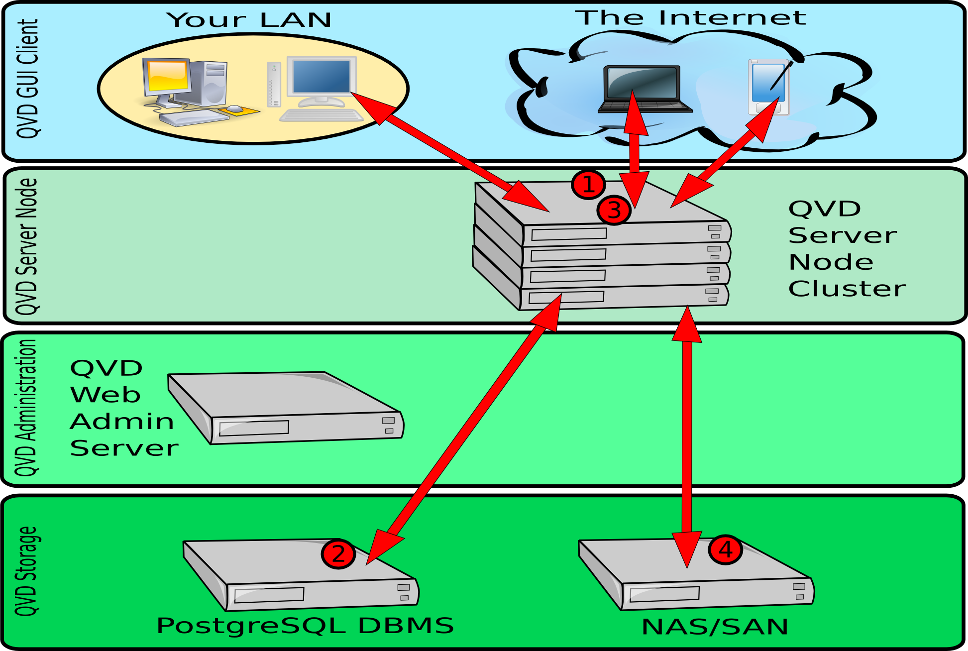
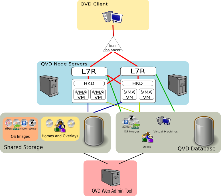
In the above diagram, we can see the interactions between the client application, the server nodes, the shared storage and the PostgreSQL database.
-
Once authenticated, the server and the client renegotiate an NX protocol connection secured by SSL. The client is able to connect to a loaded desktop inside the assigned virtual machine that is running in the server node.
-
Before any connection from the client, the server node loads an image from the shared storage in a virtual machine. The shared storage is usually accessed from a network filesystem mounted by NFS. When the virtual machine is started for a specific user, the personal directory of the user is created (later the significance of this is explained - depending on whether you use KVM or LXC). This is also stored in a shared network resource. By maintaining the start image of the user, the OSF and overlays inside the shared storage, QVD is able to automatically guarantee that the user is still able to access the same desktop regardless of the server node it connects to. This provides tolerance to failures and redundancy.
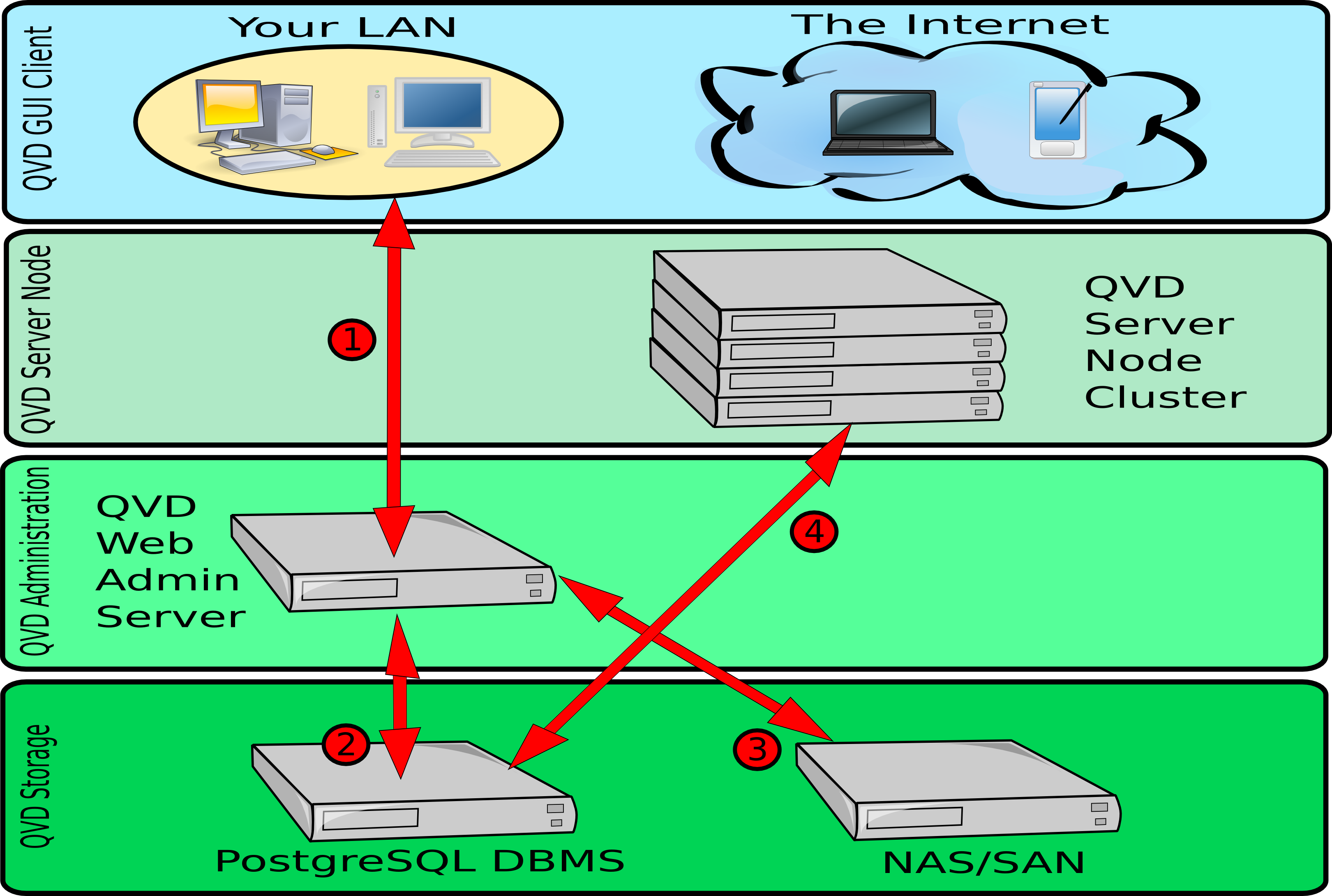
In the previous diagram, we can see the different interactions that are involved in the functioning of QVD’s web administration tool, the WAT. The WAT interacts exclusively with the QVD-DB database, which is the one that interacts with the rest of the components of the solution. The interactions mentioned here are simplified, since there are a large number of operations that can be performed using QVD-WAT.
-
An administrator can connect to the WAT from a common web browser. The connection takes place through HTTPS. These credentials are stored in the PostgreSQL database.
-
The WAT uses the PostgreSQL database to store configuration information input by the administrator via the web interface. The WAT also extracts information, such as the state of the virtual machines, users and sessions of the database, to be presented to the administrator via the web interface.
-
The DIs available in the shared storage, can be administrated using the WAT. They can be enabled and disabled, as well as change their tags, making them available to the users. It is also possible to load new DIs from the WAT, on condition it has access to the shared storage (not shown in the image).
-
The HKD in each server node, makes requests periodically to the PostgreSQL database to collect the changes in configuration and state made by the WAT. For example, when a virtual machine is started or stopped from the WAT, this change is performed inside the database and when in the following requests of the HKD to the database the state of a virtual machine is determined to have changed, the change will be executed in one of the nodes. As we can see, the WAT does not interact directly with any server node in particular, but uses the PostgreSQL database as an intermediary.